The "E" Rig

In the tradition of Tom, K1JJ, who names his radio progeny, this transmitter shall be known as "Elizabeth".


Hopefully these pages will become a well detailed set of pages depicting the design and construction details yet another QFX project.
We start with the Power Supply and will proceed through the Modulator, Exciter/Driver, RF Deck and Control Circuitry.
Virtually all of the RF and modulator design follows the work of Steve, WA1QIX. Several of the circuits and PC boards were obtained from Steve and are tried and true designs that can be heard on the air. Other parts will be of my own design, particularly the power supply, mechanicals, construction technigues and control circuitry.
It is my intention to build this transmitter in such a way that the control circuitry uses a minimum of mechanical relays and switched connections. Rather, power will remain on and regulated all the time. RF keying will be accomplished using logical ENABLE inputs wherever possible. T/R switching and initial step-start will remain relay operated. Band switching will likely be manually switched as well. The intended result should be extremely fast, quiet T/R switching benefitting both operator and on-air listener.

Yeah!! Good luck with that. We'll see...

I start with the power supply.

Here are some details of the cabinetry.

Box frame is made of 3/4" x 3/4" x 1/8" aluminum. Bottom and side panels are drilled and tapped 6-32 as needed.

Rails are cut and milled to fit together at corners and then "Aluma Brazed". This stuff is great but requires a good, fine source of heat, as in Oxy-Acetylene.

The front panel is Black Anodized Brushed aluminum. I haven't determined what kind of rack handles I'll making yet.

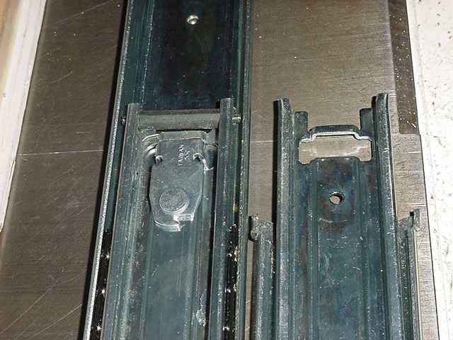
The slide rails had to be cut and remillled. Original end is on right, newly re-milled end with rail locks on left.

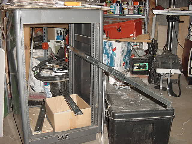
Fully extended the 3 piece slide rails will allow access beyond the rear of the units from the front of the cabinet.
More to come...