|
|
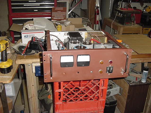
 This is the front panel in finished paint, black appliance epoxy. |
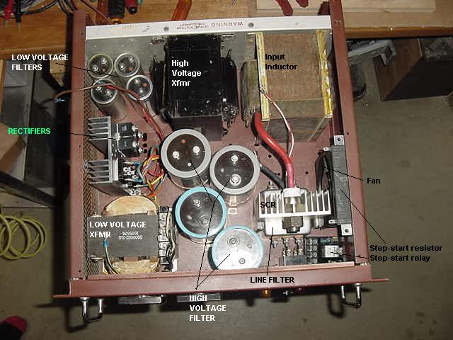
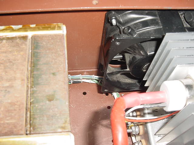
 This is the low voltage side of the supply. Transformer has two output windings, one floating driver supply and +/- 12 volt supply. AC voltage select block (120/240V) is on top of low voltage xfmr. |
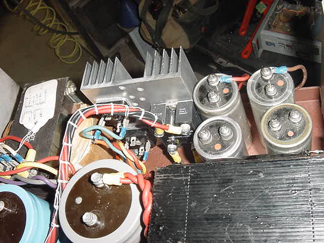 This is the rectifier block for all supply voltages. Likely the hottest part of the entire project. |
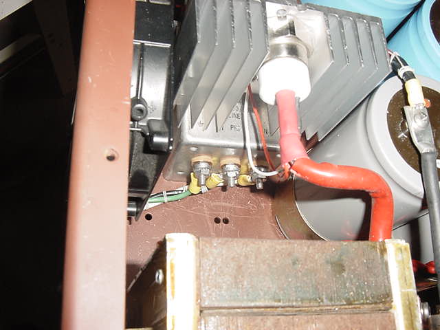
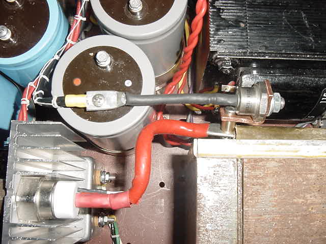 This SCR and Diode comprise the regulator block. They are bolted to the input side of the supply filter inductor. |
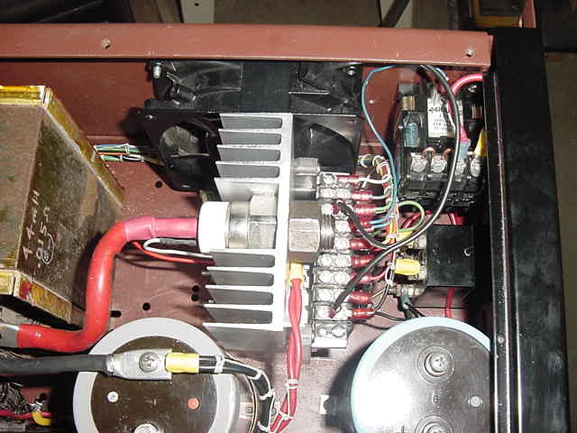 This better shows the control harness terminal strip. The step-start relay is in the corner. Step-start resitor is under the lip of the front panel. |
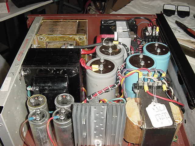
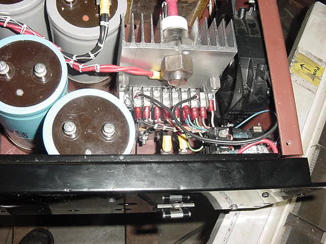 This is the regulator "module". The entire heat sink is mounted on Lexan since it has 170 rect. AC on it. |
 30 Amp AC input filter is mounted under the regulator module, between the Lexan standoffs. |
 Laced wiring runs down each side to rear panel. Lacing really "neatens" up a project. IMHO |
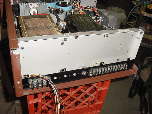 Regulator control board, low voltage fuses and all input/output will be on rear panel. |
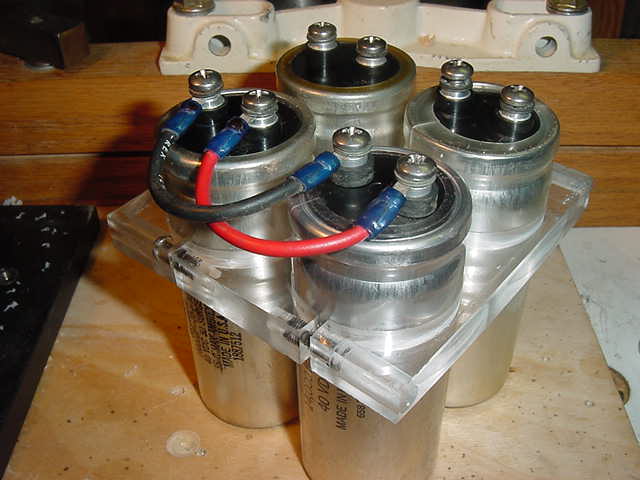 Low Voltage Supply Caps Bracket |