With the popularity of ESSB, and the resurgence of interest in AM, outboard audio gear has become more and more a part of the amateur station. Unfortunately
very few modern transmitters are set up to accept the high level output present from most audio processing equipment. Sometimes an operator can get away with
just turning down the output to achieve a reasonable level, but the residual hum and noise may remain, and the audio quality is distorted no matter how the
EQ is adjusted. Similarly, if audio levels are reduced elsewhere in the audio chain compressors and noise gate cannot be driven to functional levels.
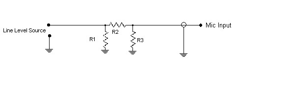
The simple solution in most cases is an easy to construct attenuator pad designed to meet the impedance requirements of the modern transcievers. Below is a
schematic and table to construct -10, -20 and -30dB "pads" intended to operate into the mic input of most radios. Typical mic input impedances for radios designed
to be driven by electret element mics are 1-2K ohms with levels in the 5-20mV (-40~-30dBu) range. Typical audio gear will have outputs capable of driving loads as low as 600
ohms and nominal outputs of 774mV at 0dB reference levels. Home audio gear uses -10dBV as a standard which is 316mV at a somewhat higher impedance, typically
2K ohms. Either way, these levels are way too high to drive a mic input. You can check the specs for your particular equipment to determine the amount of attenuation
you'll need. A handy conversion calculator for the various dB standards can be found here.
However, it turns out that a -30dB pad works for just about everybody. But all the optional info is provided here for those who enjoy their caculators.
You'll want to choose R1 such that it appears to be in the nominal load range for your audio equipment, either 600 ohms or 1-2K, depending on whether it's pro audio
or home audio equipment. At -10dB~-30dB the attenuator part of the pad is a sufficiently high value that we need not be critical regarding its loading the audio gear.
R2 and R3 can be selected from the chart below or calulated with the equation provided for a specific value. Suffice to say there is more than enough adjustabilty
in all this gear that anything within 6dB is easily compensated for with no loss in range just using the gain controls available.
These values are adjusted to nearest 10% resistor values
Atten.
R1
R2
-10dB
10K
3.3K
-15dB
10K
1.8K
-20dB
10K
1K
-30dB
22K
680
Attenuation(dB) = 20*log(R3/(R2+R3)) or R3=10^(-dB_atten/20)*R2