Summary:
Some time ago I picked up an interesting piece of gear at a hamfest. It was obviously a device to sample RF from a
transmission line but was labeled reflectomter/phase meter. It was the "phase meter" part that intriqued me most. I easily
determined how to meter the reflectometer output but the phase metering was more elusive.
In an effort to determine how the "phase metering" component of this device functions and is utilized, the device
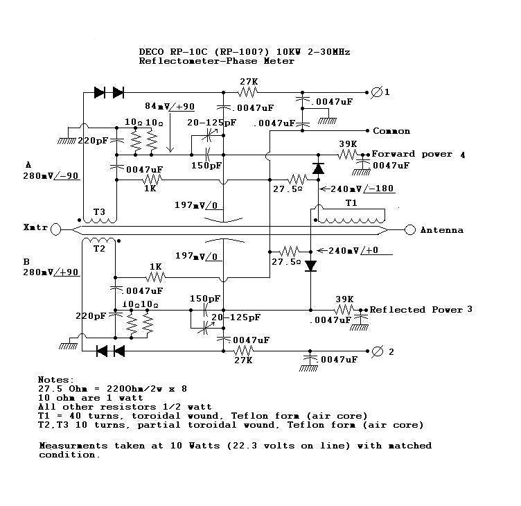
was reverse engineered and tested within the limits of my current bench setup. Per the schematic below all components were fairly
large as one might expect for a 10KW piece of gear but the principles applied could certainly be scaled down as needed and
applied to any reflectometer employing the capacitive divider/toroid type of sampling circuit commonly found in most amateur
RF metering equipment.
Testing:
The phase terminals (1 &2) develop an opposing, or differential, output voltage for almost all conditions of line impedance.
For phase measurements within the device the zero degree "reference voltage" was taken just after the first voltage sampling
capacitor off the line = 197mV. Test level was 10 watts, or 22.3 Volts of RF on the line at 14 MHz. Antenna load was 50
ohms, direct or matched through a C-L-C "T" type antenna tuner. Mismatched conditions were simulated with the antenna tuner.
The dynamics of the voltages at A and B were the focus of these investigations. The nature and operation of the forward
and reflected metering sections, and variations thereof, have been very well documented over the years and need no further
discussion here, except for one notable clarification.
Most literature states that the forward voltage and current are summed by virtue of their being in phase. This seems obvious
and even intuitive, however, in the metering of these power components the sampling of these "forward" components must be 180
degrees out of phase. Having these sample voltages out of phase enables a voltage drop to be developed across the rectifying diode
and filter capacitance, not unlike the series capacitor being charged in a voltage doubler, and hence developing a DC voltage proportional
to the series sum of the two out of phase signal components. In contrast, on the reflected side of the sampler, the same voltage and current
appear in phase and hence do not develop any differential across the summing capacitance and indicate no reflected power when the line is
terminated in a matched load. The importance of these relationships is in realizing that the voltages and currents on the line are in fact a single
voltage and current which are the vector sums of the voltages and currents on the line due to all sources of reflected and incident energy
on the line. Much literature refers to "forward" and "reflected" waves which infers an individual chaacteristic. This distinction is important in
visualizing how the resultant standing waves appear differently depending upon line length and/or meter positioning when measuring RF power in
a tranmission line. Since line length/meter location and phase are intrinsically related, so too is the resultant magnitude of the voltage and current
being measured on the line affected by these phase shifts. This would explain why your "forward" wattage seems to vary as your "reflected" wattage
varies or why your readings change when different length jumpers are inserted in the line.
An excellent amateur reference on the subject of transmission lines is
Reflections; Tranmission Lines and Antennas by Walter Maxwell, W2DU,
Findings:
All measurments were referenced to the RF voltage present at the sampling capacitance (estimated about 2pF) off the line. This is shown as
197mV, 0 degrees, near the center of the schematic below.
Under matched conditions, voltages A and B are rectified and summed with the reference voltages to yield equal and opposite
voltages at terminals 1 and 2. At 10 watts through the reflectometer, this was approximately + and - 280mV DC, unloaded.
As the antenna load was varied, it appeared that both the +/- 90 degree phase shift as well as signal amplitude varied as
expected at A and B. For A: phase shift approached 0 as load became inductive, and = 0 when open and = 180 degrees when seeing
a short. The exact opposite appeared for the voltage at B.
This would lead one to expect a continuous and predictable range of DC voltage at terminals 1 and 2 for metering, but this
as not the case. Due to the phase shifting and summing affects of other voltages on the line and within the circuitry the
ultimate output from terminals 1 and 2 is useful, sensitive and accurate for values of SWR within 3:1. Beyond this range,
the outputs appear not very useful, although further evaluation under use may reveal some more predictable character.
As a matched load condition is approached the outputs reach equal and opposite values indicating a purely resistive load
has been achieved. Even when reflected power appears to be zero, the phase outputs reveal even miniscule reactance in the load.
We presume this is due to the fact that the associated rectification diodes are being utilized well into their conduction range
and the resultant DC voltages are being summed to zero, indicating a purely resistive load. In contrast, the diodes associated
with the reflected power detection ceased to conduct well before the load was matched to a purely resistive value resulting in
a dead band in detecting very small values of reflected power.
It will be interesting to see how this sensitive device performs in indicating small load variations associated with
weather, movement and other affects in the field of an active antenna.
Application:
It would seem simple enough to add these outputs together in a voltage divider and deliver them to a zero center meter
indicating C and L, or Lead and Lag, etcetera, on either side of zero. Why then are they not summed already in the detection
circuitry? Given the nature of generating an output even when the load is matched and sensitivity to minute changes in load
impedance, it suggests that some active circuitry be placed at the observable end of the metering lines. Such circuitry
needs to develop an output proportional only ratio of the inequality of the two values, since their absolute magnitude can
vary greatly from minimum power to 10KW. Development of such a comparator circuit will ensue.
Update: 4/2010.
I have had this in use for some time now and note the following.
1) As suspected, when the reflected power reads nothing, zero, nada... there's still a lot going on with the load impedance that's seen
only in the Phase metering. In fact, reflected power can read zero for fairly wide excursions of inductive or capactive phase shift. I attribute
this to having relatively equal Resistive and Reactive mismatches that simply sum to zero "relfected" power at that specific metering point on
the feedline. However, only one setting exists on the tuner where both Phase AND Reflected Power are simultaneously zero, and when so tuned,
the output, or forward power, is exactly peaked and power readings are the same at ALL points on the line feeding the tuner. I believe too, that
the antenna system when so tuned performs a little better, but that's purely a subjective perception.
There is also no more "slight difference" when tuning up on the dummy load and switching back to the antenna
2) I have reversed one pair of phase detection diodes and apply each phase output to the opposite sides of a single, center zero meter. I found having
the diodes arranged in a series loop, as shown in the schematic, caused a DC offset between phases and two outputs that could not be summed and varied
proportionately with applied power. It was essentially a useless configuration, which must have had some solution as one time. Having no luck finding the
original metering circuit to which this bridge was attached, my solution seemed to solve several problems quite readily.
. By now comparing voltages of common polarity and offset, any power level can be easily nulled without rebalancing any metering. A potentiometer, with it's wiper grounded,
now bridges the Phase meter for nulling out any differences due to diode dissimilarities.
Bottom Line:
I REALLY, REALLY like having this metering capability in my station. The ability to see when the load is truly resistive, and perfectly matched, is very comforting.
Kinda of like adding a scope after only having metering, I wouldn't want to be without it.
Errata:
The manufacturer of this device appears to be a part of history. This device was originally developed under contract for
the U.S. Navy. Its chief designer was Raymond C. Van den Heuvel who currently works with neural networks and bionic
engineering.